


Will Light Gun Mods Damage Electronics? Safe Mod Guide
Table of Contents
Will Light Gun Mods Damage Electronics? The Honest Answer
How to Mod a Sinden Light Gun Without Frying the Board
Safe Disassembly: Clips, Pins and Cable Routing
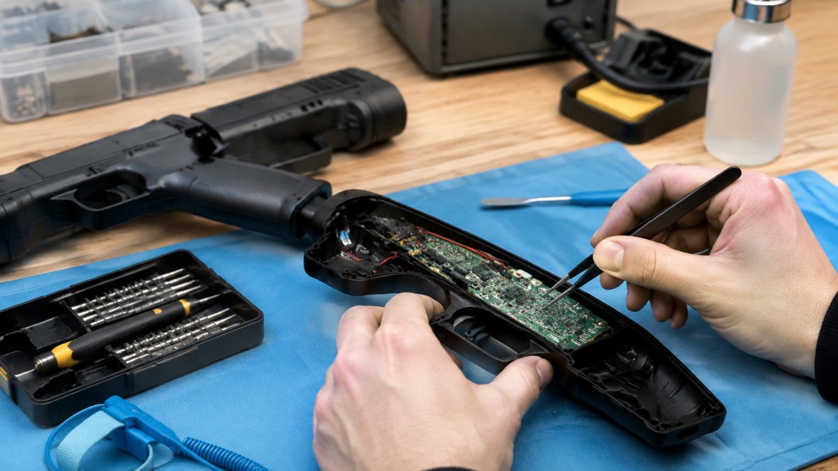
Soldering New Buttons Without Bridging Pads
Retro Shooter Light Gun Customization: What Changes and What Doesn't
Light Gun Electronics Safety Tips: Voltage, Grounding and USB Load
Voltage Regulation for IR Sensors
USB Power Draw vs Controller Port Limits
Common Mistakes That Actually Damage Light Gun Electronics
Troubleshooting Signal Interference and Tracking After a Mod
Long-Term Wear: PCB Traces, Thermal Stress and Resale Value
How Soldering Affects PCB Traces
Thermal Stress and Component Longevity
Resale Value and Reversibility
Conclusion: Mod With Confidence, Not Carelessness
Frequently Asked Questions
Last Updated: October 4, 2026
Will Light Gun Mods Damage Electronics? The Honest Answer
Will light gun mods damage electronics? In most cases, no, if you follow basic safety rules.
Here is the short version: a light gun mod damages electronics when it pushes current where it should not go. A bridged solder pad, a reversed wire, or a sensor fed the wrong voltage can kill a board in seconds.
Below, we break down each risk, show you how to avoid it, and explain what actually changes inside the gun. The goal is simple: mod with confidence, not carelessness.
Key Takeaway Most light gun failures trace back to three things: bridged solder joints, wrong voltage to the IR sensor, and USB ports that cannot supply enough current. Fix those three and you avoid almost every damaged board.
How to Mod a Sinden Light Gun Without Frying the Board
Modding a Sinden light gun safely means working slowly, checking continuity before powering up, and never forcing clips or pins. The process is not hard, but it rewards patience over speed.

Safe Disassembly: Clips, Pins and Cable Routing
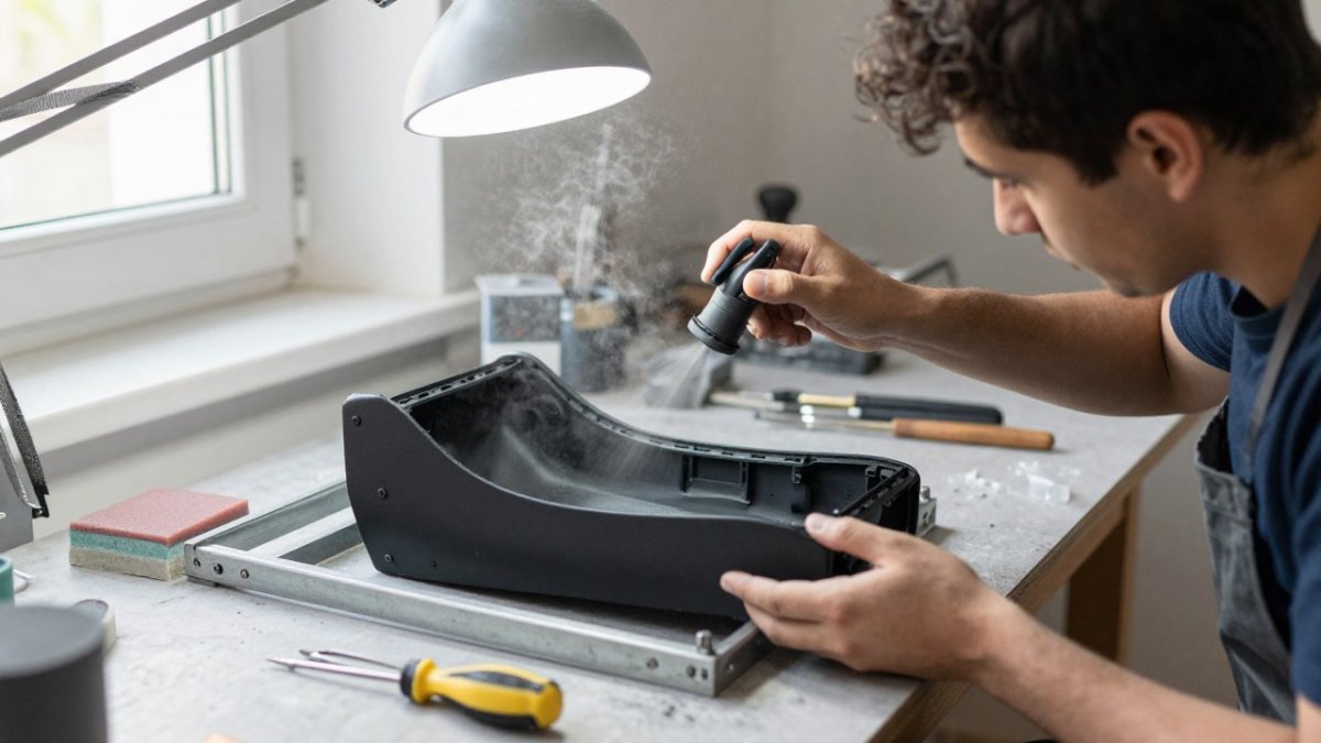
Start by unplugging everything. Then work through the shell in order:
Remove screws and keep them in a magnetic tray
Ease plastic clips apart with a spudger, not a flathead
Photograph cable routing before you unplug anything
Note which connector goes to the IR sensor and which goes to the trigger
Set the board on an anti-static mat
The thing nobody tells you about disassembly is that the clips break before the screws strip. A spudger spreads the load; a screwdriver concentrates it and snaps the tab.
Soldering New Buttons Without Bridging Pads
A bridged pad is the number one cause of dead light gun boards. Two solder points touch, current takes a shortcut, and a component burns out.
Keep your iron tip clean and tinned. Use thin solder. Touch the pad and pin for a second, add solder, then pull away. Check each joint with a multimeter in continuity mode before you reconnect power. If two neighboring pads beep, you have a bridge. Wick it off and try again.
Retro Shooter Light Gun Customization: What Changes and What Doesn't
Retro Shooter light gun customization changes the shell, the grip, and the trigger feel. It does not change the core tracking electronics unless you deliberately rewire them. That distinction matters for anyone worried about damage.
Our Retro Shooter mod kits swap the outer shell for designs like a pulse rifle or a shotgun body. The board, sensor, and wiring stay where the factory put them. So the electrical risk stays low, and the visual upgrade is dramatic.
What does change:
Weight and balance in your hand
Trigger travel and button feel
Cable routing through the new shell
What does not change:
The IR sensor position relative to the lens
The USB interface and power draw
The firmware and tracking logic
Pro Tip Before you close a new shell, route the cable the same way the factory did. A cable pinched against a screw post can wear through its insulation over months of use and cause a short.
Light Gun Electronics Safety Tips: Voltage, Grounding and USB Load
Light gun electronics safety tips come down to three checks: correct voltage, solid grounding, and enough USB current. Get these right and your mod will run cool for years. But most guides stop at "check your voltage" without explaining what that means for the specific components inside a light gun. This section goes deeper.
Voltage Regulation for IR Sensors
IR sensors are fussy about voltage. Feed one too much and it fails fast. Most sensor modules expect a steady low voltage, and any spike can cook the emitter. But the real problem is not just the absolute voltage, it is the fluctuation.
A typical IR sensor module in a light gun runs on 3.3V or 5V, depending on the design. The USB port supplies 5V, but that 5V is not perfectly stable. Under load, it can sag to 4.75V or spike to 5.25V. For a sensor that expects 5V ±5%, that is right at the edge.
If your mod adds a sensor, do not tap raw USB power. Use a regulator.
Pro Tip If you are unsure whether your sensor needs a regulator, check its datasheet. If it lists an absolute maximum voltage rating close to 5V, add one. The cost is a few dollars; the cost of a fried sensor is a new gun.
USB Power Draw vs Controller Port Limits
Every device on a USB bus shares the available current. Add a rumble motor, an LED strip, and a brighter sensor, and you can exceed what the port provides.
A standard USB 2.0 port supplies 500mA (0.5A) at 5V. USB 3.0 ports typically supply 900mA (0.9A). Many game console controller ports are even more limited, some supply only 100mA to 250mA per port.
How much does a light gun draw? A basic light gun with an IR sensor and a microcontroller might draw 100-200mA.
Watch for these signs of a power problem:
The gun disconnects mid-game
Tracking stutters under load
The controller feels warm near the connector
Other USB devices on the same bus behave erratically
If you see any of these, move the gun to a powered USB hub. A powered hub supplies its own current, so the controller port is not strained.
Watch Out Never power a modded gun from an unregulated adapter. If the adapter outputs more than the board expects, the first component in the circuit takes the full hit and fails instantly. Always use a regulated power source.
Common Mistakes That Actually Damage Light Gun Electronics
The mistakes that damage light gun electronics are predictable. Common issues include:
Soldering with the board still plugged in
Skipping the continuity check before power-up
Using a wall adapter with the wrong voltage
Forcing a connector in the wrong orientation
Leaving a stray solder blob loose inside the shell
A common mistake is testing a fresh solder joint by plugging the gun straight into the console. One wrong bridge and the console port takes the hit too. Always test on a bench supply or a cheap powered hub first.
Troubleshooting Signal Interference and Tracking After a Mod
Signal interference after a mod usually means a loose ground, a pinched cable, or a sensor that shifted during reassembly. Tracking problems are rarely caused by the mod design itself.
Work through this order:
Symptom | Likely Cause | Fix |
Cursor jumps | Loose ground wire | Re-seat ground, check continuity |
No tracking | Sensor cable unseated | Reseat connector, check pins |
Works then drops | USB power draw too high | Move to powered hub |
Drifts off target | Sensor shifted in shell | Re-align sensor to lens |
Random clicks | Bridged trigger pad | Reflow and recheck joint |
Start with the simplest cause. Nine times out of ten, a reseated connector fixes it. Only open the shell again if the simple fixes fail.
Long-Term Wear: PCB Traces, Thermal Stress and Resale Value
Long-term wear on a modded gun comes from heat and repeated flex, not from the mod itself.
How Soldering Affects PCB Traces
Every time you solder a component to a PCB, you apply heat. That heat does two things: it melts the solder, and it expands the copper traces and the fiberglass substrate at different rates. This is called thermal expansion mismatch.
Vintage controller PCBs are particularly vulnerable. They were designed for a single factory soldering process, not for repeated rework. The copper traces are often thin, sometimes only 0.5 oz copper (about 17.5 µm thick), and the pads are small.
A common pattern is that a mod works fine for months, then suddenly fails. The cause is often a trace that finally cracked after repeated thermal cycling.
Thermal Stress and Component Longevity
Heat does not just affect traces. It also stresses the components themselves. Electrolytic capacitors, for example, have a rated lifespan that halves for every 10°C increase in operating temperature. If your mod adds components that run hot, or if you block airflow inside the shell, you can shorten the life of every component on the board.
Keep these points in mind:
A cold solder joint runs hotter than a clean one because it has higher resistance
Thin traces near the connector flex every time you plug in, so strain relief matters
Heat shrink on exposed wire slows wear and prevents shorts
A gun that runs cool lasts longer
If you are adding a regulator or other active components, place them where they can dissipate heat. Do not bury them under the board or against the shell. Use thermal tape or a small heatsink if necessary.
Resale Value and Reversibility
Resale value is the other factor. A clean, reversible mod holds value. A gun with scorched traces and melted plastic does not.
But reversibility is not just about keeping parts. It is about how you mod. If you cut traces or drill holes, you have permanently altered the board.
Documentation also matters. Take photos before and after. Note which wires go where. If you sell the gun, include the original parts and a note explaining the mod.
For broader guidance on safe electronics work, the electronics safety resources from the IEEE cover grounding and handling practices that apply directly to hobby builds.
Conclusion: Mod With Confidence, Not Carelessness
The real challenge with light gun mods is not the mod itself. It is the small mistakes that turn a fun project into a dead board. Check your joints, watch your voltage, and respect the USB current limit.
At Tcarterdesigns, we build our kits around that idea. Our custom light gun mods for Retro Shooter hardware swap the shell without touching the tracking electronics, so you get a pulse rifle or shotgun look with the factory board untouched. The kits are easy to install, and the design keeps your wiring where it belongs.
Ready to upgrade your arcade setup? Shop the Tcarterdesigns collection and give your light gun the look it deserves.
Frequently Asked Questions
Are 3D printed light gun shells safe for internal electronics?
Yes, when the shell is designed for the specific board it houses. The risk comes from poor airflow and pressure on components, not the plastic itself. Choose shells with internal standoffs that match your Retro Shooter or Sinden board, leave the IR sensor window unobstructed, and avoid over-tightening screws that flex the PCB. Tcarterdesigns kits are made for Retro Shooter internals, so mounting points line up and the board is not stressed. If a shell traps heat near the voltage regulator, add a small vent or run shorter sessions.
Do custom light gun mods affect tracking accuracy?
They can if the mod blocks the IR sensor or changes the gun's weight distribution. The sensor needs a clear line of sight to your screen or sensor bar, so any shell design that covers the lens will cause dropouts. Weight shifts matter less for LED-based systems but can tire your arm during long sessions. After installing a mod, run a tracking test in your usual game. If the cursor jitters, check that the sensor window is unobstructed and that internal wiring is not pressing against the board.
How do I safely disassemble a light gun for modification?
Power down, unplug USB, and remove the magazine or battery pack first. Work on a soft mat so screws and clips do not roll away. Use a plastic spudger to release clips rather than a metal flathead, which can scratch traces or short pins. Photograph each layer as you go. Keep screws in labeled cups because lengths differ and a long screw in a short hole can crack the PCB. Before reassembly, check continuity on any wire you moved.
Can soldering new buttons to a light gun cause short circuits?
Yes, if solder bridges two pads or a stray wire strand touches a neighbouring trace. Use a fine tip, lead-free solder, and flux sparingly. Tin the pad and the wire separately, then join them with a quick touch. Inspect under bright light or a magnifier for bridges. A multimeter continuity check between adjacent pins will catch most shorts before you power up. If you are not confident soldering, choose a mod kit that uses plug-in connectors instead.
Shop
Comments